laserstencils
When designing electronic circuit boards, sometimes the chips you'd really like to use only come in small packages (such as QFN, etc). This makes hand soldering difficult, time-consuming, and error-prone. With access to a laser cutter you can make a stencil for solder paste, and with a toaster oven you can reflow solder, making these packages accessible for hobby projects or prototypes.
This checklist is on github at https://github.com/jnoss/laserstencil-checklist, comments and pull requests welcome if you have feedback!
How to laser cut solder paste stencils and toaster oven reflow
outline
- photos
- materials list
- pre-stenciling:
- layout PCB and generate paste layer Gerber
- have the board fabricated
- convert Gerber to SVG
- make stencil:
- shrink pads to account for laser kerf
- laser cut from Mylar
- prepare toaster oven reflow
- set up toaster oven
- prepare components
- stencil
- prepare for solder paste
- apply paste
- lift stencil
- inspect pads
- continue toaster oven reflow
- place components
- re-inspect board, re-check placement and polarity
- toaster oven reflow
- inspect board
- final steps/cleanup
- solder any PTH components necessary
- clean stencil
- clean board
- bonus: things that can go wrong (more photos)
- advanced options
- enhanced tools
- sources
photos
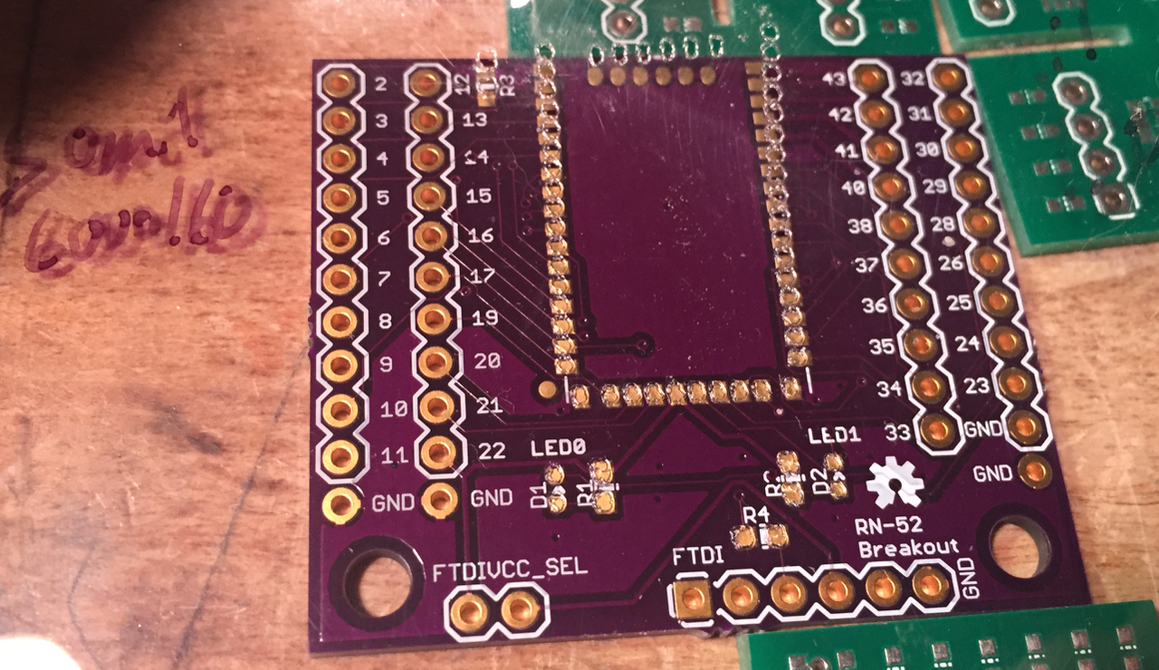
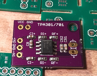
This is a photo showing how to line up the stencil with the board. On the upper right you can see the stencil still in the air.
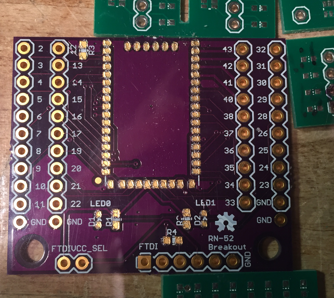
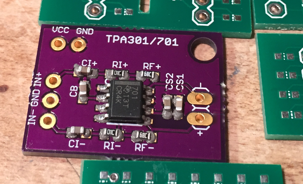
This is the stencil flat on the board. You can see the holes all line up with the pads. Note also the green PCBs alongside - those help keep the stencil flat and in full contact with the board to be stenciled.
This is after stenciling - all pads have a deposit of solder paste.
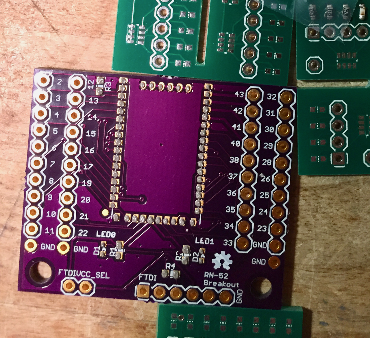
Different board, same idea - this is after stenciling.
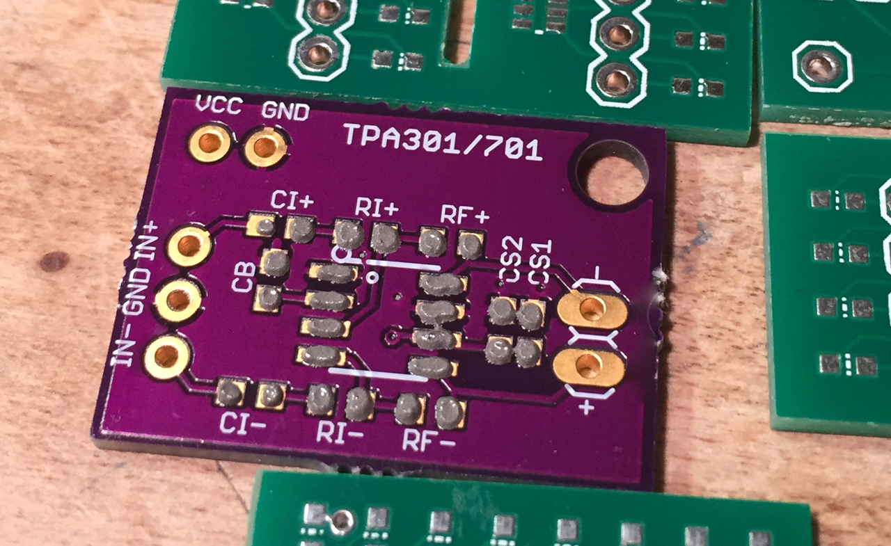
Components placed.
After reflow - all pads soldered.
materials
- software:
- PCB editor such as EAGLE
- gerbv
- Inkscape
- optional python script for shrinking size of pads in SVG, https://github.com/jnoss/svg-pad-shrink
- tools
- laser cutter
- toaster oven (note, this needs to be a dedicated solder-reflow toaster oven -- once you have used it near solder, you cannot use it for food again)
- thermocouple temperature sensor (optional)
- IR heat gun (optional)
- hand soldering iron (for any rework necessary)
- squeegee (such as a plastic squeegee for painting/spackling)
- magnifying glass / loupe
- un-populated PCBs of same thickness as the board to be soldered (to use as spacers when stenciling)
- parts
- PCB to be stenciled
- components to be soldered onto board
- materials
- clear Mylar (available at art supply stores, also called Dura-Lar; example from Dick Blick, I've used 3mil and it works fine; see reference for more detail on stencil thickness and wall shape
- supplies
- desoldering wick (just in case)
- lead-free small-diameter solder (for rework if necessary)
- isopropyl alcohol
- kimwipes, or other, from Digi-Key or VWR, for cleaning PCB after soldering
- solder paste, preferably low melting point such as LTLFP, on Digi-Key (low melting point of 281 F, easier to reach in toaster oven)
- scotch tape
How to laser cut solder paste stencils and toaster oven reflow
- photos (see above)
- materials list (see above)
- pre-stenciling
- layout PCB and generate paste layer Gerber
- layout PCB in your chosen editor (EAGLE, etc)
- use only rectangular pads, not rounded edges, those will make things more difficult later
- follow PCB checklist https://github.com/jnoss/pcb-checklist to make sure it's ready for fabrication
- print paste layer to Gerber (called tcream in EAGLE); use cam job such as SparkFun's; we'll only use the .GTP layer. These are the places that we want to put solder paste
- print 1-1 on paper and verify it looks correct
- have the board fabricated
- this can be via OSHPark, or on your Othermill, etc
- convert Gerber to SVG
- open Gerber .GTP layer in gerbv, and export to SVG
- layout PCB and generate paste layer Gerber
- make stencil:
- shrink pads
- because the laser beam has a finite width (or kerf) we need to shrink all of the pads before we can cut them. If we cut the stencil as-is, the laser will cut away too much material. The kerf is around 10mil on the ones I've used, so each pad will be too big by at least 5mil in each direction. This means the pads would risk running into one another for fine-pitch parts. So, we'll shrink the pads first:
- for small boards you can do this manually in a vector editor (Inkscape)
- if you have windows you can use Pentalogix ViewMate and shrink the pads Pentalogix and Adafruit tutorial
- or you can use the python script I wrote https://github.com/jnoss/svg-pad-shrink which will shrink all rectangular pads by the number of mils you specify
- because the laser beam has a finite width (or kerf) we need to shrink all of the pads before we can cut them. If we cut the stencil as-is, the laser will cut away too much material. The kerf is around 10mil on the ones I've used, so each pad will be too big by at least 5mil in each direction. This means the pads would risk running into one another for fine-pitch parts. So, we'll shrink the pads first:
- laser cut this from Mylar
- you'll likely need to make a few test cuts to get the settings for your laser / your thickness of Mylar
- write the laser cutter settings you used on the mylar next to each test stencil with sharpie, so you can keep track (or write a run # and keep a corresponding log book)
- also vary the amount you're shrinking the pads - this is where the svg-pad-shrink script comes in handy, can just re-run the script and get a new file to cut
- settings on the Lasersaur at Artisan's Asylum were 6000/50 using 50mil shrunken pads
- check that all holes are clear of incomplete cuts (can check this with fine tweezers)
- check that holes don't run into each other - may need to shrink more or adjust cut speed
- bring the PCB with you (or a paper printout) and overlay the stencil to compare if it looks good
- shrink pads
- prepare toaster oven reflow
- set up toaster oven
- any toaster oven will work for LTLFP but may have trouble with higher-temperature paste, keeping in mind that ICs are usually rated for ~20seconds in the high temperature zone - if your toaster oven takes too long to get to the solder melting temperature you can risk damaging your ICs - use these only for prototypes! heat-related effects could only manifest later or when under load. For production it's necessary to follow the datasheet temperature reflow curve, which usually means a real reflow oven.
- I cover the rack with tinfoil so that tiny PCBs don't fall through
- I also thread a thermocouple in the side of the door, and angle it to touch the tinfoil next to where I'll place the PCB
- prepare components
- make sure you have all the components in stock
- print a board layout on paper (zoomed in) showing the location of all components, including polarity
- verify polarity markings on any polarized components and ensure when placing them they are correct
- set up toaster oven
- stencil
- prepare for solder paste
- arrange blank PCBs around the PCB to be stenciled so that there is a flat surface all around it, taping the blank PCBs down if necessary (leave a route to slide the stenciled PCB out without jostling it)
- lay the stencil on top of it, align the stencil holes with the pads, and tape the left edge of the stencil to your workbench - you'll use this like a hinge to lift the stencil off of it
- double check to make sure stencil lines up correctly with PCB
- apply paste
- hold down the stencil so it doesn't move
- apply solder paste to left side of stencil (or, if you want to cheat, gently apply on top of all the holes if using a syringe applicator)
- keep holding the stencil down on the board, and squeegee in a smooth motion from the left to the right, making sure to get paste into all of the holes - see next step before lifting squeegee!
- when lifting squeegee, make sure to hold the stencil down - surface tension will tend to lift the stencil with the squeegee, which you want to avoid as it can smear the solder paste deposits
- lift stencil
- taking care not to let stencil buckle, lift from the right - I hold it down to the right of my board, lift the right edge, curl it up, and then lift the rest of the way - try for one clean upward lift (hinge) to release the paste from the stencil
- un-tape the stencil from the left (or just hinge it over to the left if you have space) and set it out of the way
- inspect pads
- all pads should have a dot of paste on them. it's ok if they aren't perfectly lined up -- surface tension when it reflows will pull everything into place, chips will seat themselves and align to pads (you can watch this through the glass door of your toaster oven)
- make sure not too much paste is bridging pads - again, this will bead up due to surface tension and a little bit won't be a problem, but, if there's too much it can cause bridges. Pay special attention to places where you won't be able to see or fix bridges - such as between pads of a QFN or under a BGA.
- prepare for solder paste
- continue toaster oven reflow
- place components
- being careful of polarity, place components according to the board layout.
- for small 0402s make sure both ends seat into the paste at either side - need surface tension to keep them from standing up on end (never happened to me but I've read of it)
- re-inspect board, re-check placement and polarity
- this is the last chance to fix any component placement or polarity - after this point it'll be hot air or soldering tweezer rework to fix anything
- toaster oven reflow
- heat toaster oven up to ~200
- set populated board into toaster oven gently to not displace any components (the solder paste usually has pretty good tack for several hours, see the datasheet)
- turn toaster oven up past the melting point of your solder paste
- watch the thermocouple temperature
- when it's close to melting point, watch for the matte solder paste pads going shiny molten solder - they'll usually not all go simultaneously but usually within a few seconds
- watch to make sure all pads go molten shiny solder (I let it go 5 seconds more or so) and then
- turn off the toaster oven and gently open the door - you want this to cool off as fast as possible (to comply as much as possible with the components' reflow profiles from their datasheets)
- watch thermocouple, or board with IR heat gun, and watch the molten shiny pads for when they go to just shiny solder pads -- ie, when they solidify -- and then gently remove the board from the toaster oven and set on your workbench to cool the rest of the way
- inspect board
- once the board is cool enough to handle, inspect for shorts (solder bridges), missing connections (especially on pads that touch ground planes - these you may need to hit with a soldering iron and fine gauge solder as the copper plane has a larger thermal mass)
- test with a multimeter for any shorts, it's possible to have them invisible under an IC
- place components
- final steps/cleanup
- solder any PTH components necessary
- clean stencil
- use isopropyl alcohol and kimwipes, clean both sides of stencil
- clean board
- use isopropyl alcohol and kimwipes
things that can go wrong

This is a board where the stencil wasn't properly aligned when stenciling - note all the solder paste deposits are mis-aligned, in this case need to clean off the board with isopropyl alcohol and a kimwipe and start over.
This is a test stencil where not enough paste made it through. Options are to try and make sure you're using enough paste when doing the squeegee step, making sure you're covering each hole as you squeegee. Another cause could be using a stencil that's too small - you may need to try larger holes. It's a balance between keeping the holes from running together when you lasercut them and getting enough paste out of them when you stencil them.
advanced options:
- use 2 different temperature solder pastes and double-side placement of components (or, can try with just surface tension)
- make a frame for the stencil to improve lifting off your board
enhanced tools:
- reflow oven for temperature ramp more appropriate to datasheets for components
- aquarium pump pick & place (such as via http://www.instructables.com/id/Circuit-Board-Lab-POV-Business-Card/step5/Build-an-SMD-Vacuum-Pick-and-Place-Tool/)
- cardboard palette with cut tape for component placing
alternative to lasering your own stencils (AKA the easier but less fun approach):
- use OSH Stencils https://www.oshstencils.com
Sources:
- Stencils: https://learn.adafruit.com/smt-manufacturing/laser-cut-stencils
- EAGLE cam job: https://learn.sparkfun.com/tutorials/using-eagle-board-layout/generating-Gerbers
Other references:
- detailed explanation of stencil thickness and wall shape: http://www.qualiecocircuits.co.nz/stencil-technology-other-aspects.htm
- https://www.sparkfun.com/tutorials/58
- https://www.sparkfun.com/tutorials/383
- http://www.instructables.com/id/Polyimide-Kapton-PCB-Solder-Paste-Stencil/
- http://www.instructables.com/id/SMT-Solder-Paste-Stencil-Production-Jig-using-a-/
- http://hackaday.com/2016/05/10/tools-of-the-trade-component-placing/